Disclaimer
All consequences are the reader’s responsibility. Read carefully and proceed at your own risk.
Parts of this article were generated with AI. The remainder is a concise compilation and paraphrase of publicly available resources and the author’s hands-on checks. I only performed light functional tests on modules I obtained; I did not perform production integration or RF compliance testing. Fibocom FGxxx series modules used for development or as surplus may have missing documentation or unexpected hardware revisions. Do not change RF parameters or key radio settings on public networks — that may disrupt public radio systems and could be illegal.
The notes below are general guidance and quick functional checks based on public information. They may not apply to every SKU, firmware or carrier configuration. Verify against Fibocom’s official documentation and local regulations before using in production.
Module overview
The FG160 family uses LGA packaging and a mobile-style outer enclosure similar to common 520 form-factor designs. Some NA SKUs may lack bands such as n1 or n79 depending on the exact variant. Many pins on the module are reserved or not exposed on some carrier boards, so available functions depend on the specific breakout or evaluation board.
When mounted on an M.2 adapter configured as an M.2 B-Key, the FG160 functions as a cellular modem on carrier boards.
Operating modes
Switch USB/network modes with AT+GTUSBMODE=<mode number>. Factory default is commonly 32.
| Mode | Description |
|---|---|
| 17 | Diag + Modem + AT + Pipe + RMNET + ADB |
| 18 | Diag + Modem + AT + Pipe + ECM + ADB |
| 20 | Modem |
| 21 | Modem + AT |
| 22 | Modem + AT + RMNET |
| 23 | Modem + AT + ECM |
| 24 | RNDIS + Modem + Diag + ADB |
| 28 | MBIM |
| 29 | MBIM + AT + Diag |
| 30 | MBIM + Modem + Diag + AT |
| 31 | Diag + Modem + RMNET + DPL + QDSS + ADB (QCOM reserved for internal debug) |
| 32 | Diag + Modem + AT + Pipe + RMNET |
| 33 | Diag + Modem + AT + Pipe + ECM |
| 34 | Modem + AT + Pipe + RMNET |
| 35 | Modem + AT + Pipe + ECM |
Common choices for general use: 17, 18, 24 and 32. If you run a PCIe network interface while using USB-based RNDIS, set the USB mode to 24. Using MBIM may require the host adapter to set the module PCIe interface to End Point (EP) mode.
AT-based dialing (quick reference)
Install the necessary drivers and available documentation first. As a practical reference, Waveshare’s M.2-to-Gigabit-Ethernet adapter notes are useful: https://www.waveshare.net/wiki/5G_M.2_TO_Gigabit_ETH
The FG160 firmware may include an automatic connect feature. Enable auto-connect with:
AT+GTAUTOCONNECT=1
If auto-connect does not work, use the following AT commands to check status and bring up data interfaces:
|
|
M.2 / network interface
M.2 B-Key adapter
You can place the module on an M.2 B-Key adapter (m2-bkey). Some adapter designs rework or remove certain antenna/feed traces; a controlled PCB stack (for example ~0.8 mm thickness and appropriate layer stack) helps match impedance and mechanical tolerances.
Gerber and layout references (shared link): https://wwbk.lanzouq.com/b00uzitkpe (password: h4h8)
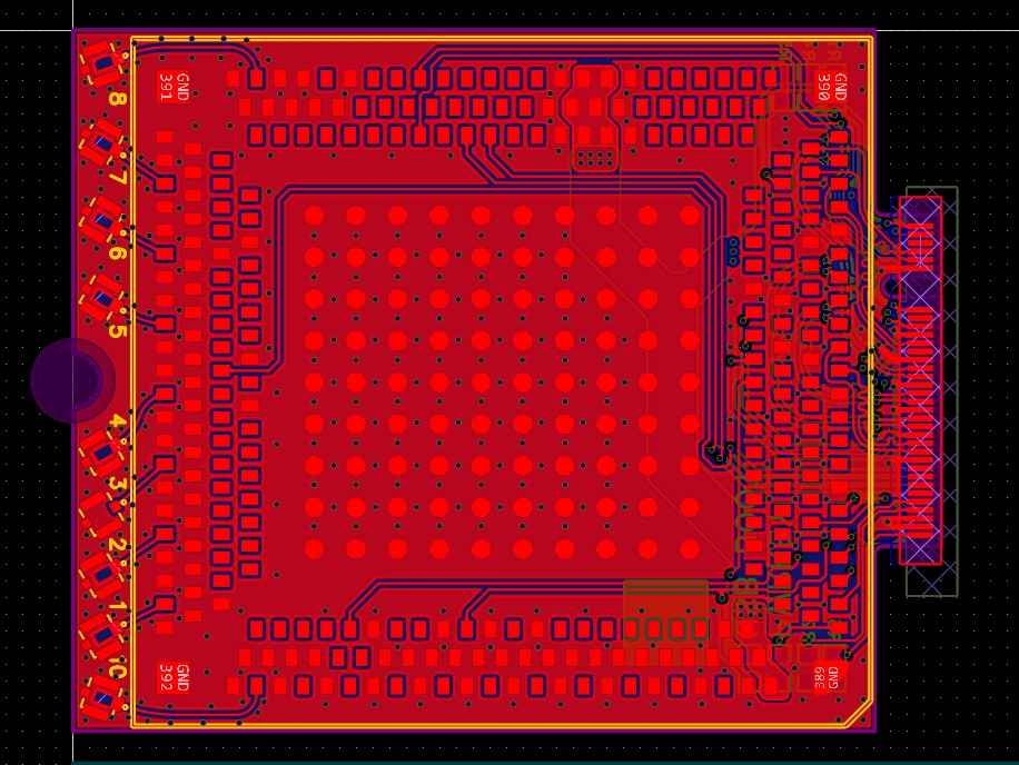
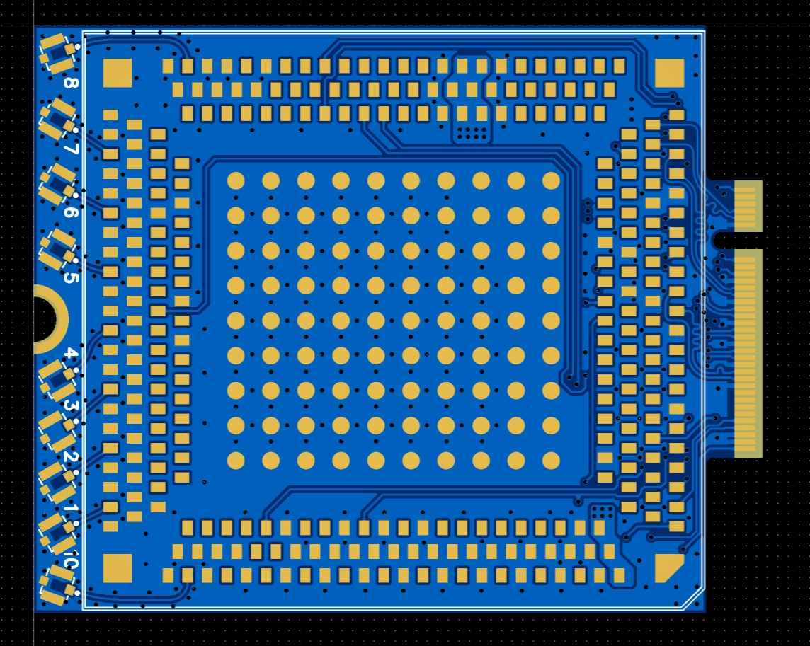
Soldering recommendation: use lead-free or low-temperature paste and a controlled hot-plate/reflow process. A dedicated BGA oven is not strictly required if your reflow process is controlled.
For NA SKUs (EAU-00/01/02/31) commonly populate antenna pads 2,4,6,8; some variants (EAU-10/11) may require populating pads 1–8 depending on SKU.
If the module is used on a carrier that provides M.2-to-Ethernet or PCIe bridging, backside component soldering is usually not required for basic operation. If the module will operate as a PCIe End Point, ensure the carrier config sets correct power and signal routing.
Network (Ethernet) adapter
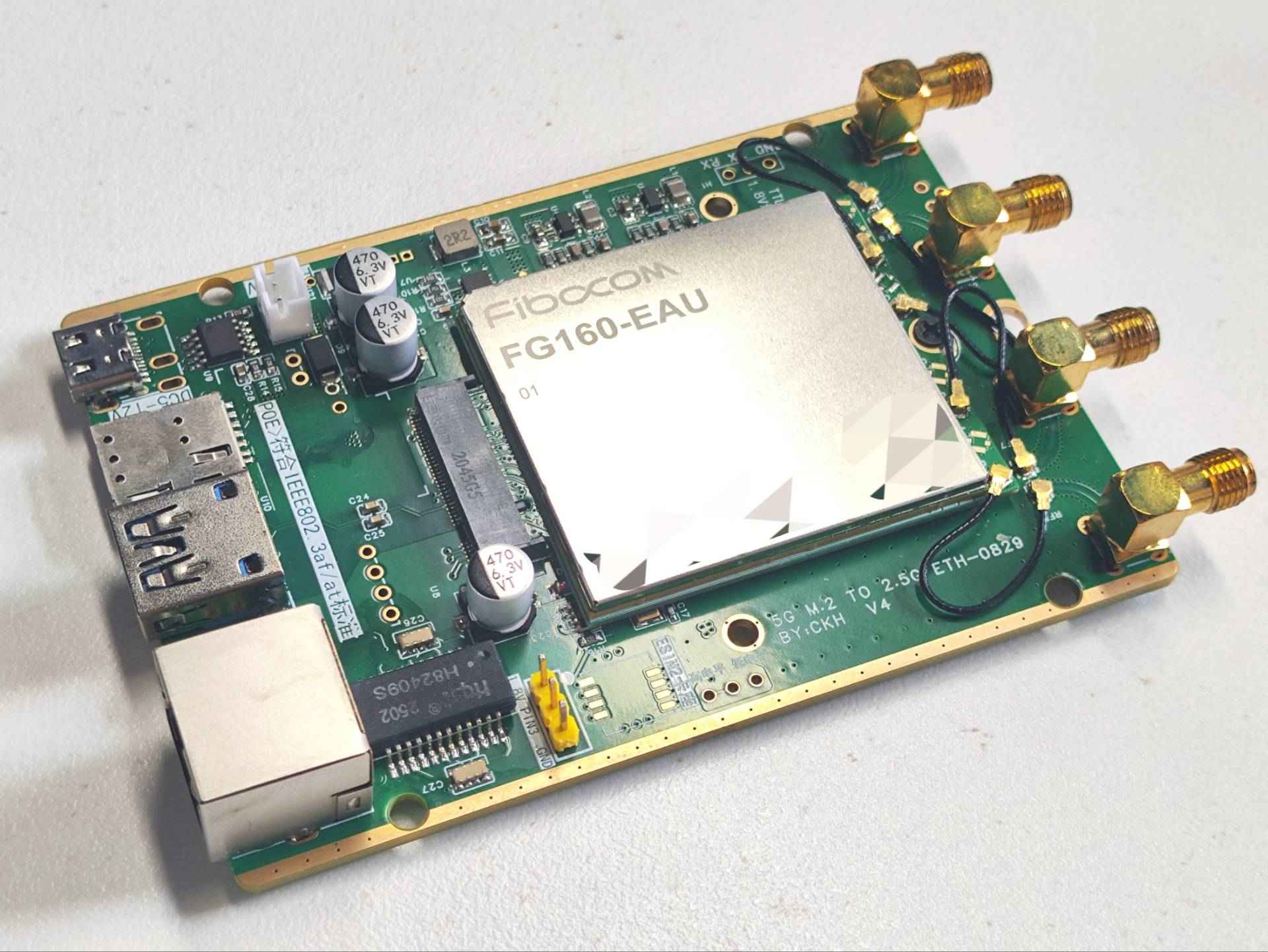
For M.2 B-Key to Ethernet adapters, a common PHY choice on the carrier board is the Realtek RTL8125. Leave enough clearance for the module and wider components on the carrier.
Web UI
Some evaluation or carrier boards with FG160 include a simple web UI. When present it is usually reachable at 192.168.1.1 (default password often 12345678). Surplus units may have modified firmware; access methods vary by board.
Other notes
FG160 modules expose many interfaces and debug capabilities that are not necessarily user-serviceable. Advanced firmware, calibration and RF parameter changes should only be performed with official documentation and appropriate authorization.